Capacitor Styles and Packaging
Capacitors are available in a wide range of capacitance values, from just a few picofarads to well in excess of a farad, a range of over 10(^{12}). Unlike resistors, whose physical size relates to their power rating and not their resistance value, the physical size of a capacitor is related to both its capacitance and its voltage rating (a consequence of Equation ref{8.4}. Modest surface mount capacitors can be quite small while the power supply filter capacitors commonly used in consumer electronics devices such as an audio amplifier can be considerably larger than a D cell battery. A sampling of capacitors is shown in Figure 8.2.4 .
Figure 8.2.4 : A variety of capacitor styles and packages.
You are watching: 8.2: Capacitance and Capacitors
Toward the front and left side of the photo are a variety of plastic film capacitors. The disk-shaped capacitor uses a ceramic dielectric. The small square device toward the front is a surface mount capacitor, and to its right is a teardrop-shaped tantalum capacitor, commonly used for power supply bypass applications in electronic circuits. The medium sized capacitor to the right with folded leads is a paper capacitor, at one time very popular in audio circuitry. A number of capacitors have a crimp ring at one side, including the large device with screw terminals. These are aluminum electrolytic capacitors. These devices tend to exhibit high volumetric efficiency but generally do not offer top performance in other areas such as absolute accuracy and leakage current. They usually are polarized, meaning that the leads must match the polarity of the applied voltage. Inserting them into a circuit backwards can result in catastrophic failure. The polarity is usually identified by a series of minus signs and/or a stripe that indicates the negative lead. Tantalum capacitors are also polarized but are typically denoted with a plus sign next to the positive lead. A variable capacitor used for tuning radios is shown in Figure 8.2.5 . One set of plates is fixed to the frame while an intersecting set of plates is affixed to a shaft. Rotating the shaft changes the amount of plate area that overlaps, and thus changes the capacitance.
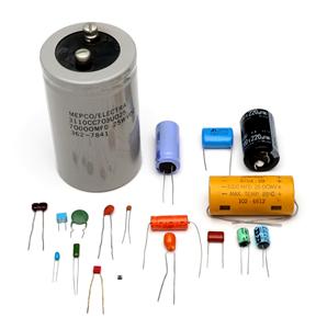
Figure 8.2.5 : A variable capacitor.
For large capacitors, the capacitance value and voltage rating are usually printed directly on the case. Some capacitors use “MFD” which stands for “microfarads”. While a capacitor color code exists, rather like the resistor color code, it has generally fallen out of favor. For smaller capacitors a numeric code is used that echoes the color code. Typically it consists of a three digit number such as “152”.
The first two digits are the precision portion and the third digit is the power of ten multiplier. The result is in picofarads. Thus, 152 is 1500 pf.
See more : Life Insurance Quotes for Seniors in USA: Your Guide to Affordable Coverage in Your Golden Years
Figure 8.2.6 : Capacitor schematic symbols (top-bottom): non-polarized, polarized, variable.
The schematic symbols for capacitors are shown in Figure 8.2.6 . There are three symbols in wide use. The first symbol, using two parallel lines to echo the two plates, is for standard non-polarized capacitors. The second symbol represents polarized capacitors. In this variant, the positive lead is drawn with a straight line for that plate and often denoted with a plus sign. The negative terminal is drawn with a curved line. The third symbol is used for variable capacitors and is drawn with an arrow through it, rather like a rheostat.
Figure 8.2.7 : An LCR meter, designed to read capacitance, resistance and inductance.
In order to obtain accurate measurements of capacitors, an LCR meter, such as the one shown in Figure 8.2.7 , may be used. These devices are designed to measure the three common passive electrical components: resistors, capacitors and inductors1. Unlike a simple digital multimeter, an LCR meter can also measure the values at various AC frequencies instead of just DC, and also determine secondary characteristics such as equivalent series resistance and effective parallel leakage resistance.
Source: https://en.congthucvatly.com
Category: Blog