Solar Efficiency Limits
It was first calculated by William Shockley and Hans Queisser in 1961. A solar cell’s energy conversion efficiency is the percentage of power converted from sunlight to electrical energy under “standard test conditions” (STC). The STC conditions approximate solar noon at the spring and autumn equinoxes in the continental United States with the surface of the solar cell aimed directly at the sun.
You are watching: Solar Efficiency Limits
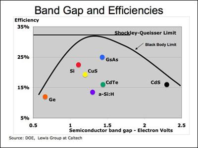
The modern SQ Limit calculation is a maximum efficiency of 33% for any type of single junction solar cell. The original calculation by Shockley and Queisser was 30% for a silicon solar cell. Current solar cell production efficiencies vary by the band gap of the semiconductor material as shown on the left. See Junctions & Band Gaps page.
The best modern production silicon cell efficiency is 24% at the cell level and 20% at the module level as reported by SunPower in March of, 2012. In a laboratory, the record solar cell efficiency is held by the University Of New South Wales in Sydney, Australia at 25%.
There are a number of assumptions associated with the SQ Limit that restrict its general applicability to all types of solar cells. Although there are numerous programs underway to find ways around the SQ Limit, it is still applicable to 99.9% of the solar cells on the market today. Top
If the theoretical limit for silicon cells is about 30%, what happens to the other 6% that is lost from the best production cell efficiency of 24%? Some sunlight is always reflected off the surface of the cell even though the surface is usually texturized and coated with an anti-reflective coating. In addition there are some losses at the junction of the silicon cell with the electrical contacts that carry the current to the load. Finally, there are some losses due to manufacturing impurities in the silicon. Top
Shown to the left is the complete spectrum of electro-magnetic radiation. The long radio waves at the right are the weakest. The most powerful rays (gamma rays) are very short and to the left.
For a semiconductor electron to move into an external load circuit, its energy level must be increased from its normal valence level (tightly bound to one atom) to its higher energy conduction level (free to move around). The amount of energy to boost it to the higher level is called the “band gap” energy. See Junctions & Band Gaps page.
Only photons with at least the band gap energy will be able to free electrons to create a current. Sunlight photons with less than the band gap energy will simply pass through the solar cell. Put in terms of radiation, all the photons in the visible spectrum are strong enough to causeelectrons to jump the band gap.
Some infrared, all microwave, and all radio waves do not have enough energy and pass right through the solar cell.
In the “sunlight energy distribution” chart to the left, only the mustard colored photons can be “absorbed” and create electricity in a crystalline silicon cell. Absorption of electromagnetic radiation is the process by which the energy of a photon from the sun is transformed into other forms of energy for example electricity or heat.
The red colored wavelenghts do not have enough energy and the yellow ones have too much energy. The yellow wavelengths are absorbed and generate electricity, but a lot of their energy is lost. That is because photons with excess band gap energy generate a free electron and a hole, but their extra energy gets dissipated as heat.
X-rays and Gamma rays have just too much energy to be absorbed at all. The mustard area is basically a picture of the SQ Limit applied to silicon as Shockley and Queisser calculated it in 1961. Top
Basically the strategies to obtain better efficiencies than the SQ Limit predicts are to work-around one or more of the critical assumptions listed above (and shown again below).
See more : Physics
1) One semiconductor material (excluding doping materials) per solar cell.
Use more than one semiconductor material in a cell.
2) One P/N junction per solar cell.
Use more than one junction in a cell – “tandem cells”.
3) The sunlight is not concentrated – a “one sun” source.
Sunlight can be concentrated about 500 times using inexpensive lenses.
4) All energy is converted to heat from photons greater than the band gap.
Combine a PV semiconductor with a heat based technology to harvest both forms of energy and/or
Use “quantum dots” to harvest some of the excess photon energy for electricity.
Top
The earliest and most frequent work around to the SQ Limit has been the use of multiple p/n junctions, each one tuned to a different frequency of the solar spectrum. Since sunlight will only react strongly with band gaps roughly the same width as their wavelength, the top layers are made very thin so they are almost transparent to longer wavelengths. This allows the junctions to be stacked, with the layers capturing the shortest wavelengths on top, and the longer wavelength photons passing through them to the lower layers.
The example of a multi-junction cell on the left has a top cell of gallium indium phosphide, then a “tunnel diode junction”, and a bottom cell of gallium arsenide. The tunnel junction allows the electrons to flow between the cells and keeps the electric fields of the two cells separate. Most of today’s research in multi-junction cells focuses on gallium arsenide as one of the component cells as it has a very desirable band gap. Performing a calculation using the SQ methodology; a two-layer cell can reach a maximum theoretical efficiency of 42% and three-layer cells 49%.
The record for a multi-junction cell is held by the University Of New South Wales (UNSW) in Sydney, Australia at 43% using a five cell tandem approach. However, the UNSW tandem cell is very expensive. In addition to the cost issue, there are other constraints that make the tandem cells complex. For example, all the layers must be lattice compatible with one another in their crystalline structure and the currents from each individual cell must match the other cells. Multi-junction cells are commercially used in only special applications because their expense currently outweighs any efficiency improvement. At the moment they are used in space where weight is most important and in concentrated PV systems where the sunlight is focused on a very small cell area requiring only small amounts of semiconductors per cell. Top
Concentrated PhotoVoltaics (CPV), in which sunlight is focused onto a small solar cell by lenses to generate more power per unit of surface area, was an early favorite to increase solar efficiency. CPV’s main attraction is that it can leverage modest “one sun” cell electricity production to a much larger scale production using relatively simple and inexpensive optical concentration.
See more : Dorohedoro: Diving into the Dark and Twisted World
Instead of a typical 6 inch by 6 inch solar cell, a 7 inch by 7 inch square plastic Fresnel (pronounced Fray-NELL) lens incorporating circular facets, is used to focus the sunlight as shown on the left. A tiny, 39% efficient multi-junction solar cell is mounted at the focal point which converts the sun’s energy into electricity. Future cell efficiencies are expected to approach 50%. The Fresnel lens concentrates the sun’s energy about 500 times its normal intensity. A number of Fresnel lenses are manufactured as a single plastic piece. The tiny solar cells are mounted on a supporting plate at locations corresponding to the focus point of each Fresnel lens. Hundreds of lenses make up a solar array mounted on a sun tracking heliostat. With a high “module efficiency” of 31%, CPV systems take up less land than traditional PV systems, use no water, and are ideal for desert type areas. See the Amonix discussion.
Despite the concentration advantages, CPV has been slow to gain market share. While the tiny solar cells use less of the expensive semiconductor materials, cost is a factor as a two-axis sun tracking heliostat is necessary to accurately keep the focus point on the solar cell as the sun travels east to west each day and north and south each season. CPV does not do well in cloudy climates as diffuse sunlight does not concentrate well. In addition, the large heliostats are not well suited for the small installations that have been the mainstream of the recent PV market. Today, CPV costs are very competitive and CPV is benefiting from growing demand for large utility size solar plants, especially in the desert areas of California, Arizona, Spain, and Australia. Top
In a regular solar cell, each photon collision generates a particle pair consisting of one free hole and one free electron. Quantum Dots are extremely small “nanocrystals” (the names are used somewhat interchangeably) interspersed in a larger semiconducting material. Quantum Dots (QDs) range between 1 and 20 nanometers in size (one nanometer is one billionth of a meter). See the two pictures from MIT on the left.
Semiconductors at this size have different physical properties than their big brothers. When photons with energy greater than the band gap energy collide with a Quantum Dot several “hot” hole/electron pairs can be created as opposed to one pair and heat. Although silicon can be used as a nanocrystal, lead selenide (PbSE) also a semiconductor, is being used more frequently as the material of choice.
Another characteristic of a Quantum Dot is that different sizes capture different wavelengths of light. Small dots capture small wavelengths and larger dots bigger wavelengths. Some researchers have figured out how to stack the dots from small to large to capture more photon energy similar to how tandem cells do (see strategy one/two above).
Once a hot electron is created inside a Quantum Dot, it stretches its lifetime as much as a 1000 times before it cools. The electrons like to stay inside the QD. One of the challenges was to figure out how to extract the hot electrons from the QDs. No solar cells produced prior to December, 2011 have quantum efficiencies greater than 100 percent.
Quantum efficiency (not to be confused with solar cell efficiency) per the National Renewable Energy Laboratory (NREL) located in Boulder, Colorado, is the “ratio of collected charge carriers (electrons or electron holes) to incident photons”. In layman terms – its the ratio of the number of electrons produced in a solar cell to the number of the sun’s photons hitting the cell.
Researchers from the NREL have reported quantum efficiencies of 114 percent in solar cells “excited” from photons from the high-energy region of the solar spectrum. That is from the near ultraviolet through the visible light spectrum – 350 to 700 nanometers. See the sunlight spectrum chart above.
Energy is always conserved. The extra electrons come from the extra energy left over after the initial photon-electron collision. Light waves below 700 nanometers do not have enough energy to dislodge more than one electron-hole pair.
This process, which creates more than one electron-hole pair from a single photon, is called “multiple exciton generation” (MEG) by NREL.
Shown at the left is an electron wave function in a Quantum Dot (i.e. the probability of an electron being in any specific location at any given time – purple is low probability and white is high probability).
The practical upper limit for “thin film” solar cells is thought to be about 20%. The upper limit using Quantum Dots is thought to be about 30%. It should be emphasized that the research into Quantum Dots is at a very basic stage of demonstrating scientific principles. No one at this time has actually made a pre-production Quantum Dot solar cell. Production solar cells using Quantum Dots are thought to be about 10 years into the future.
Top
Source: https://en.congthucvatly.com
Category: Blog
This post was last modified on Tháng Mười 5, 2023 7:15 chiều
If you're a 60-year-old man considering a $500,000 life insurance policy, you're likely wondering about…
Choosing the best life insurance provider is a crucial decision, especially in Canada, where numerous…
Navigating the U.S. financial landscape as a foreigner can be complex, and life insurance is…
American Family Insurance is a well-established provider known for its comprehensive range of insurance products,…
While banks primarily offer financial services like checking and savings accounts, loans, and credit cards,…
Chase, a well-known financial institution, offers a wide range of financial products and services. But…